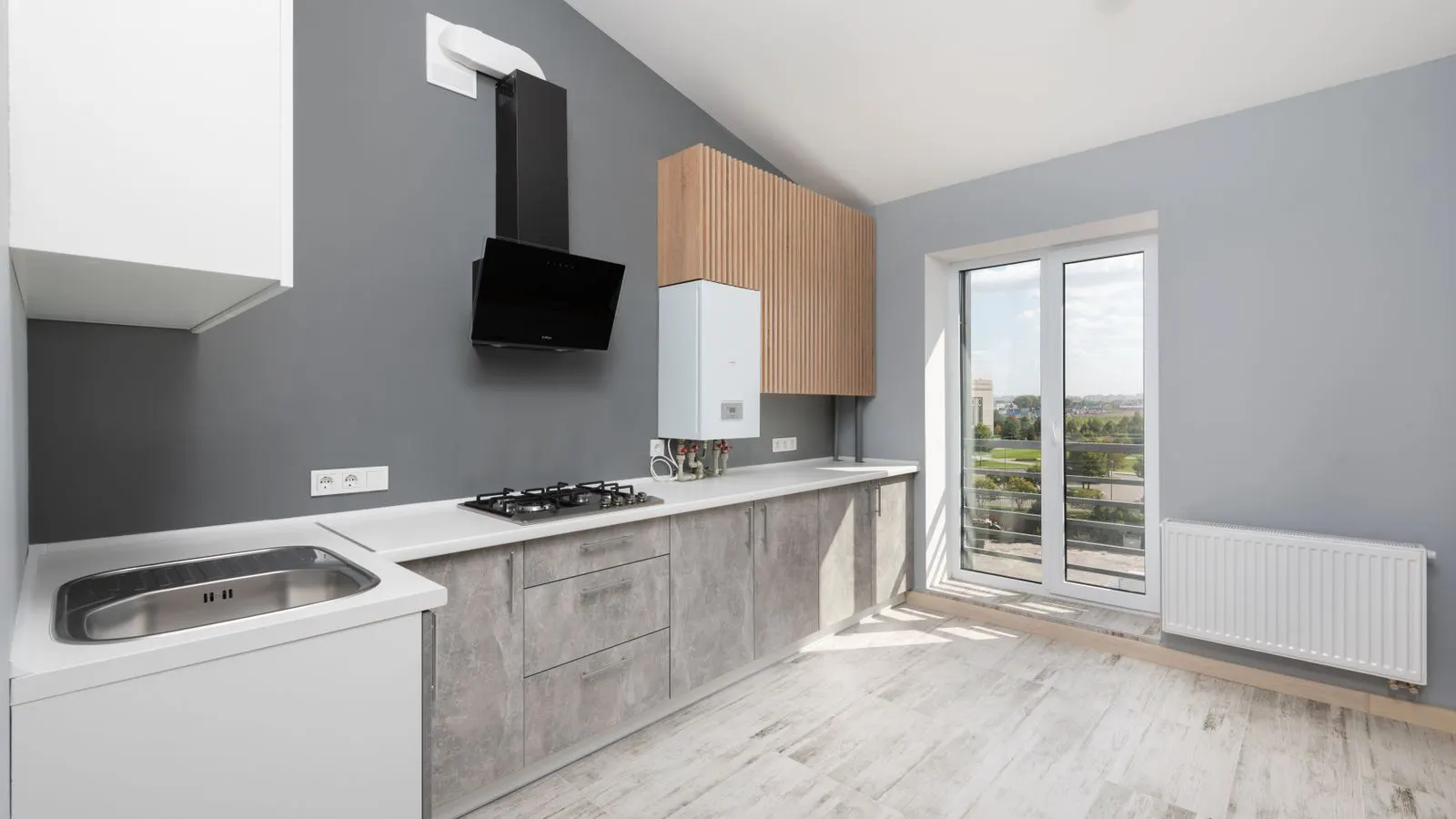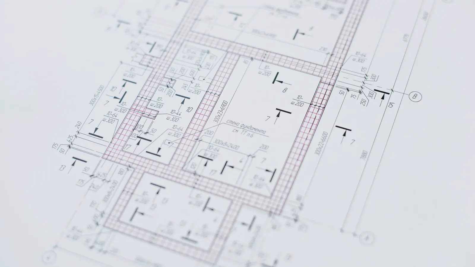
A pre-installation checklist confirms clearances, utility connections, and site preparation before equipment arrives. This guide provides a numbered, theme-based audit for buyers and engineers to prevent delays, rework, and safety issues.
- Verify all equipment dimensions, clearance requirements, and utility connections before delivery.
- Confirm utility capacity, routing, and access points match the equipment specification sheets.
- Inspect the subfloor, walls, and structural supports for readiness.
- Document all pre-installation checks with photos and written notes.
- Assign a single point of contact to coordinate with the installer, utility providers, and building management.
Why the pre-installation checklist matters
Equipment delivery without verified clearances and utilities causes rework. Installers arrive, measure, and find that a range needs three more inches of side clearance or that the gas line is routed through a structural beam. The result is a stalled installation, changed equipment, or compromised safety.
A pre-installation checklist is not a formality. It is a controlled handoff between the design phase and the build phase. It confirms that every item on the equipment schedule has a physical location, a utility connection, and a compliant path for service.
This guide uses a numbered audit format. Each item is grouped by theme: clearances, utilities, site preparation, documentation, and coordination. Use it as a copyable checklist for new kitchens and major retrofits.
Clearances: confirm every equipment position
Clearances are the first thing to verify. The equipment manufacturer’s installation manual defines the minimum distance from hot surfaces to walls, counters, and other equipment. These distances are not decorative. They protect building materials, personnel, and equipment serviceability.
- Measure the installed position of each unit. Place the equipment on the floor or use a laser measure to mark the exact footprint. Record the length, width, and height of each item. Compare these numbers to the equipment schedule.
- Check the clearance to the nearest wall. For hot cooking equipment, the manufacturer specifies the distance from the front of the unit to the nearest combustible surface. For ovens and ranges, this is often measured to the front of the appliance, not the control panel.
- Check the clearance to adjacent equipment. Two ovens side by side need the manufacturer-specified gap. If the gap is too narrow, service access is blocked. If the gap is too wide, heat loss increases and the room may not meet the design intent.
- Check the clearance above and below. Overhead storage, ductwork, and exhaust hoods must not block the equipment’s service area. Below, the subfloor must support the unit’s weight and any dynamic loads from agitation, such as in mixers or dishwashers.
- Check the clearance to doors and access panels. Walk-in refrigerators, blast chillers, and dishwashers need door swing clearances. If a door hits a wall or a counter when opened, the unit is not usable.
- Check the clearance for service access. Most commercial equipment requires a minimum working distance on at least one side for filter changes, burner cleaning, or electrical access. If a unit is against a wall, confirm that the service side is the one with access.
Red flags:
- The equipment footprint on the drawing does not match the physical space.
- The clearance to a combustible wall is less than the manufacturer’s minimum.
- The service side of the unit is blocked by a fixed counter or wall.
- The door swing of a refrigerator or dishwasher is blocked by another unit.
Utilities: verify capacity, routing, and access
Utility planning determines whether equipment can operate at all. A range without a gas line is a decorative object. A dishwasher without a dedicated electrical circuit will trip breakers. The utility audit is a physical inspection of every connection point.
- Verify the gas supply. Confirm the gas line is present at the equipment location. Check the line size, the shut-off valve, and the pressure rating. For multiple gas units, the line must be sized for the combined draw. If the line is undersized, the equipment will flame out or operate at reduced capacity.
- Verify the electrical supply. Confirm the voltage, phase, and amperage at the disconnect. Match these numbers to the equipment nameplate. A three-phase motor connected to a single-phase line will not start. A dedicated circuit is required for most heavy equipment.
- Verify the water supply. Confirm the hot and cold water lines are present at the equipment. For dishwashers and pot sinks, the flow rate and pressure must meet the manufacturer’s specification. For espresso machines, the water quality and pressure are critical.
- Verify the drain. Confirm the drain is present and sloped correctly. For dishwashers and pot sinks, the drain must be a dedicated line or have an air gap. A shared drain with other fixtures can cause backflow and contamination.
- Verify the exhaust and ventilation. Confirm the exhaust hood is present, the ductwork is installed, and the make-up air system is sized. Without adequate make-up air, the exhaust system will pull unbalanced air from outside, creating negative pressure in the kitchen.
- Verify the fire suppression. Confirm the fire suppression system is installed and the nozzles are positioned per the manufacturer’s specification. For commercial kitchens, this is a non-negotiable safety item.
Red flags:
- The gas line is present but the shut-off valve is missing or inoperable.
- The electrical disconnect is a standard outlet rather than a hardwired disconnect.
- The drain is shared with a hand sink rather than a dedicated line.
- The exhaust hood is installed but the ductwork is not connected to the roof termination.
- The fire suppression nozzle is blocked by a shelf or a duct.
Site preparation: confirm the building is ready
Site preparation is the physical condition of the floor, walls, and ceiling. If the subfloor is not level, a dishwasher will not operate correctly. If the wall is not plumb, a hood will not sit flush. If the ceiling is not finished, the exhaust ductwork cannot be installed.
- Inspect the subfloor. The subfloor must be level within the manufacturer’s tolerance. For commercial equipment, a tolerance of one-eighth inch over four feet is typical. If the floor is uneven, the equipment will rock, which causes mechanical wear and seal failure.
- Inspect the walls. The walls must be plumb and finished. For areas near hot equipment, the wall material must be non-combustible. For areas near water, the wall material must be water-resistant.
- Inspect the ceiling. The ceiling must be finished and accessible. The exhaust ductwork must be routed through the ceiling. The fire suppression nozzle must be accessible for inspection.
- Inspect the structural supports. Confirm that the structural supports are adequate for the equipment weight. A walk-in refrigerator on a mezzanine requires a load calculation. A blast chiller on a concrete floor requires a check for water damage.
- Inspect the access points. Confirm that the access points for equipment delivery are clear. A walk-in refrigerator must be delivered through a door that is at least as wide as the unit. A walk-in refrigerator with a door width of 36 inches cannot be delivered through a 30-inch door.
Red flags:
- The subfloor is uneven beyond the manufacturer’s tolerance.
- The wall is not plumb, causing the equipment to sit at an angle.
- The ceiling is not finished, blocking the exhaust ductwork.
- The structural supports are not adequate for the equipment weight.
- The access points are blocked by storage or other equipment.
Documentation: record every check
Documentation is the legal and operational record of the pre-installation process. Without it, disputes over who was responsible for a defect are difficult to resolve. A photo of a gas line with a shut-off valve is worth more than a verbal confirmation.
- Create a pre-installation log. Record the date, the inspector, and the location of each check. For each item, record the measured value, the required value, and the pass/fail status.
- Photograph every utility connection. Photograph the gas line, the electrical disconnect, the water supply, the drain, and the exhaust hood. Include the nameplate of the equipment in the photo.
- Photograph every clearance. Photograph the equipment footprint on the floor with a laser measure visible. Photograph the clearance to the nearest wall. Photograph the service access area.
- Photograph the site preparation. Photograph the subfloor with a level visible. Photograph the walls with a plumb bob. Photograph the ceiling with the exhaust ductwork.
- Sign and date the checklist. The checklist must be signed by the buyer’s representative and the installer’s representative. Both parties must agree that the site is ready for equipment delivery.
Red flags:
- The pre-installation log is incomplete or missing.
- The photographs do not show the nameplate or the measured value.
- The checklist is signed by only one party.
- The pre-installation log does not include the date and time.
Coordination: assign a single point of contact
Coordination is the human process that ties the physical checks to the installation schedule. If the gas line is not ready, the installer cannot install the range. If the electrical disconnect is not ready, the installer cannot install the dishwasher. A single point of contact prevents the installation from stalling.
- Assign a single point of contact. This person is responsible for coordinating with the installer, the utility providers, and the building management. This person is the single source of truth for the installation schedule.
- Schedule a pre-delivery meeting. This meeting is held one week before equipment delivery. The installer, the buyer, and the building management attend. The meeting reviews the pre-installation checklist and confirms that all items are complete.
- Confirm the delivery window. The delivery window must be coordinated with the utility providers. If the gas line is being installed, the delivery window must be after the gas line is complete. If the electrical disconnect is being installed, the delivery window must be after the electrical disconnect is complete.
- Confirm the service access. The service access area must be clear. If a unit is against a wall, the service side must be accessible. If a unit is in a corner, the service side must be accessible.
- Confirm the post-delivery inspection. The post-delivery inspection is held immediately after equipment installation. The inspector verifies that the equipment is installed per the pre-installation checklist. The inspector signs the post-delivery inspection log.
Red flags:
- There is no single point of contact for the installation.
- The pre-delivery meeting is not scheduled.
- The delivery window is not coordinated with the utility providers.
- The service access area is not confirmed.
- The post-delivery inspection is not scheduled.
Utility capacity table
The table below shows typical utility connections for common commercial kitchen equipment. Use this table as a reference, but always verify against the equipment nameplate and the manufacturer’s installation manual.
| Equipment Type | Gas | Electrical | Water | Drain | Exhaust |
|---|---|---|---|---|---|
| Range | Yes | No | No | No | Yes |
| Oven | Yes | No | No | No | Yes |
| Dishwasher | No | Yes | Yes | Yes | No |
| Walk-in Refrigerator | No | Yes | No | No | No |
| Pot Sink | Yes | Yes | Yes | Yes | No |
| Espresso Machine | No | Yes | Yes | Yes | No |
Red flags:
- The equipment type is not listed in the table.
- The utility connection is not present at the equipment location.
- The utility connection is present but the capacity is insufficient.
- The utility connection is present but the routing is not accessible.
Final verification
The pre-installation checklist is complete when every item is verified, documented, and signed. The equipment is ready for delivery when the clearances are confirmed, the utilities are ready, the site is prepared, the documentation is complete, and the coordination is in place.
The cost of a missed item is not just the cost of rework. It is the cost of a delayed opening, a compromised safety item, and a compromised equipment performance. The pre-installation checklist is the control that prevents these costs.
Use the checklist as a living document. Update it as the installation progresses. Keep it with the equipment manual and the as-built drawings. It is the record that the kitchen was ready when the equipment arrived.
Frequently asked questions
How early should the pre-installation checklist be completed?
The pre-installation checklist should be completed at least two weeks before equipment delivery. This allows time for the utility providers and the building management to complete any necessary work.
Who should sign the pre-installation checklist?
The buyer's representative and the installer's representative should sign the pre-installation checklist. Both parties must agree that the site is ready for equipment delivery.
What if the utility connection is not ready?
If the utility connection is not ready, the equipment cannot be installed. The installation schedule must be adjusted to accommodate the utility work. The pre-installation checklist must be updated to reflect the new schedule.
Can the pre-installation checklist be used for retrofits?
Yes. The pre-installation checklist can be used for retrofits. The retrofit must be assessed to determine if the existing utilities and clearances are adequate for the new equipment.
How long should the pre-installation documentation be retained?
The pre-installation documentation should be retained for the life of the equipment. It is a record of the installation conditions and is useful for troubleshooting and maintenance.